Hurrah !
After months of work on the Agayon, I can present some significant improvements ! This article is a little bit longer than the previous ones but it worth the read!
Software updates !
During the past few weeks, the code base of the Agayon has been updated. I forked my own project, r1d2 to update it. The new repository is named r1d3. I hesitated a long time before forking it. As the hardware base of the Agayon completely changed, I preferred to change the code name to maintain coherence between hardware and software.
The update aims to provide
- Python 3 support only
- OpenCV 4 support for
- Face recognition
- Sign tracking
- Face/hand detection and tracking
- Better XMPP ad hoc support
- I2C support
- Hardware switches support.
XMPP Ad hoc commands
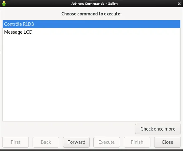
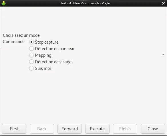
As I made tests with SLeekXMPP to control the bot, I observed some problems with Gajim. The Ad-Hoc extension allows one to send commands to an XMPP bot. R1D3 displays the following menus and submenus (in french):
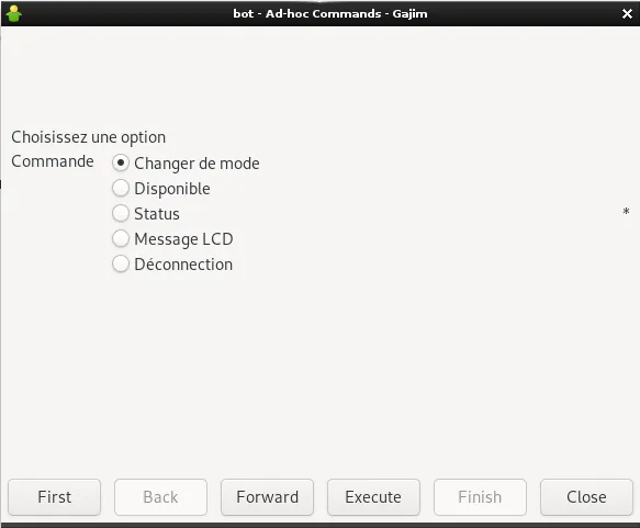
When I try to use the "execute" button, SleekXMPP start a new session and Gajim complains that the session identifier has changed. I reported the problem to SleekXMPP and its fork SliXMPP. The XMPP community is great and Maxime Buquet responded quickly. To quote him, there are two problems (see the bug report for the whole explanations):
- Slixmpp shouldn't assume execute is the start of a command
- I don't see a place in the XEP that says that next or execute can be equivalent to complete. What to do?
He sent an email on the "Standards" mailing list and some responses followed. It seems difficult to fix the protocol at the moment without breaking compatibility. Maxime proposed a patch to fix Slixmpp and it should work on SleekXMPP. For now, I just don't use the "Execute" button as "Forward" does the job. The depreciation of the "Execute action" is actually discussed.
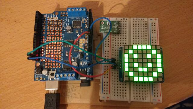
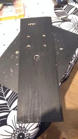
New hardware !
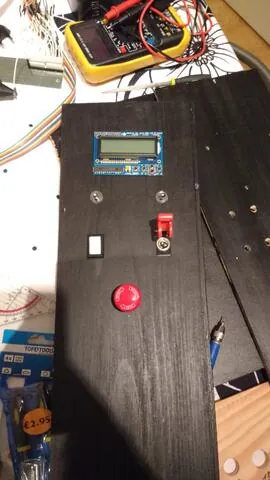
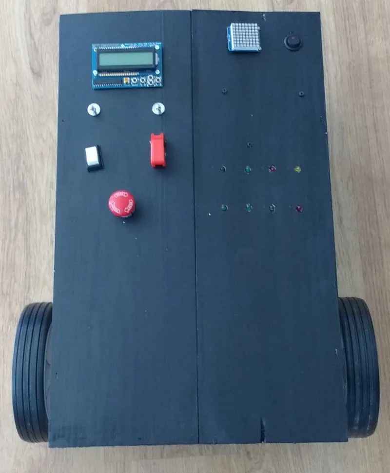
The Agayon has now 8 LEDs and 6 switches. They are placed on a control panel.
The LEDs aim to provide status information
- 5V power (orange)
- Pi powered up (green)
- I2C on the Arduino (green)
- I2C + serial on the Pi (green)
- Serial communication (green, Arduino)
- Video capture (red)
- Internet connection (blue)
- LIDAR mapping (red)
The switches aim to provide
- Power on (12V) (Ebay)
- Start R1D3 (MCHobby)
- On/Off Demo mode (Arduino) (Ebay)
- On/Off Power down (Pi) (Ebay
- Emergency stop (cut Arduino power) (Ebay)
- Movie recording (Pi)
In addition, the following hardware are also mounted to provide information and input/output. I2C addresses are displayed (0Xxx)
- I2C bicolor matrix 8x8: 0x70
- LCD with 5 buttons: 0x20
- MinIMU-9 v3 I2C Inertial measurement unit (IMU): L3GD20H (gyroscope): 0x6B, LSM303D (3-axis magnetometer and 3-axis accelerometer) 0x1D
- 6 HC-SR04 Ultrasonic sonar distance sensor for surrounding obstacle detection
- SHT71 relative humidity and temperature sensor
The documentation of the SHT71 explains why the sensor has no I2C adress.
The serial interface of the SHT7x is optimized for sensor readout and effective power consumption. The sensor cannot be addressed by I2C protocol, however, the sensor can be connected to an I2C bus without interference with other devices connected to the bus. Microcontroller must switch between protocols.
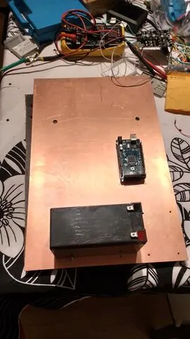
One ground to rule them all
I have been advised to use an epoxy base coated with a copper layer. The aim is to connect it to the negative pole of the battery. It is really useful because it decrease the wiring. The perfboards are fixed on metallics spacer bars to avoid shortcuts.
I2C Scans
I²C is a bus communication that allows multiple device to communicate with each other.
I2C devices are recognized by the Arduino (5V) and the Raspberry PI (3.3V) with the help of a level shifter.
I've used the I2C scanner provided by the Arduino documentation.
Arduino
Scanning...
I2C device found at address 0x1D  !
I2C device found at address 0x20  !
I2C device found at address 0x6B  !
I2C device found at address 0x70  !
done
Raspberry PI
user$ i2cdetect -y 1
     0  1  2  3  4  5  6  7  8  9  a  b  c  d  e  f
00:          -- -- -- -- -- -- -- -- -- -- -- -- --
10: -- -- -- -- -- -- -- -- -- -- -- -- -- 1d -- --
20: 20 -- -- -- -- -- -- -- -- -- -- -- -- -- -- --
30: -- -- -- -- -- -- -- -- -- -- -- -- -- -- -- --
40: -- -- -- -- -- -- -- -- -- -- -- -- -- -- -- --
50: -- -- -- -- -- -- -- -- -- -- -- -- -- -- -- --
60: -- -- -- -- -- -- -- -- -- -- -- 6b -- -- -- --
70: 70 -- -- -- -- -- -- --
Gallery
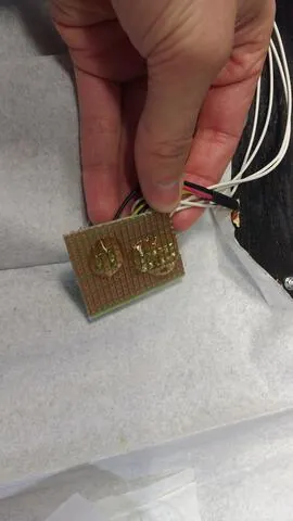
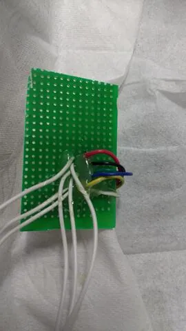
"Scaffolding" with hot glue
During the past few months, my best friend has been my hot glue gun. I was skeptical at first but really much effective and fun. I used it to insulate some connectors. In Liège, we would say "mettre une noquette de colle" which translates to "put a knob of glue".
Evolution of the frame
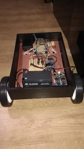
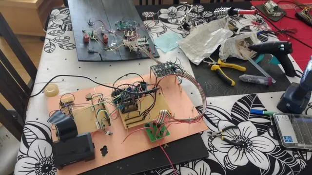
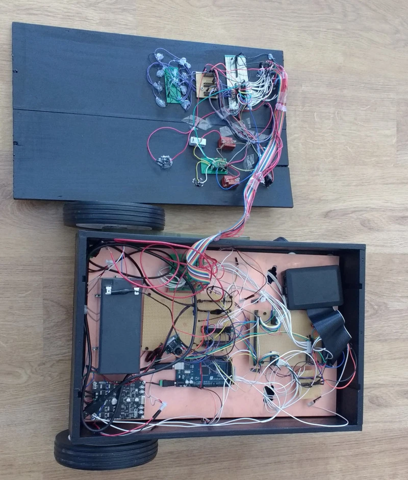
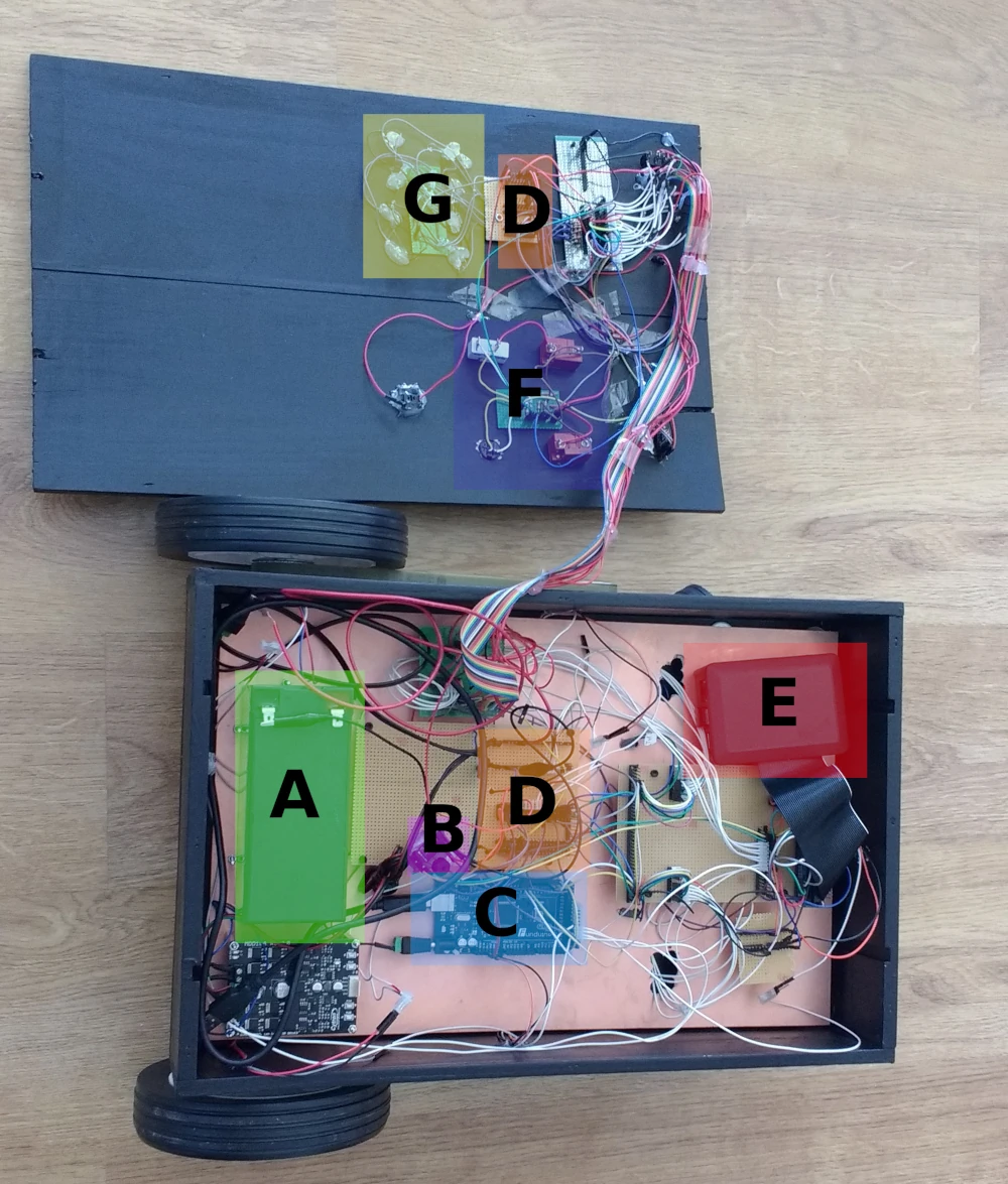
- A : Battery
- B : Level shifter between Arduino (5V) and Raspberry Pi (3.3V)
- C : Arduino Mega
- D : Power lines and I2C (12V, 5 V, 3.3V, SDA 5V, SCL 5V, SDA 3.3V, SCL 3.3V)
- E : Raspberry Pi (in his case)
- F : Buttons and their pull down (3.3V or 5V depending on the GPIO)
- G : LEDs
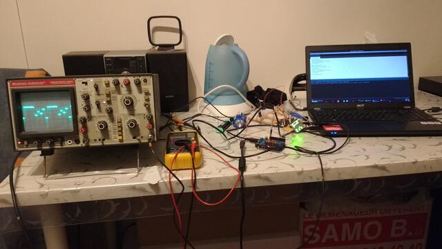
New (old) Oscilloscope
One of my colleague has been cleaning his lab, and he asked me if I was interested to have an old 20 MHz oscilloscope. I gladly accepted. It is a 34 years old Circuitmate 9020 (bought in 1985).
I will use it for I2C debugging and visualization.
Conclusion
The hardware is almost done. I am happy to have a nice reliable base. I hope to be able to drive it with my smartphone soon. I will continue the programming to add the mapping functionality and a nice demo mode.
Stay tuned !