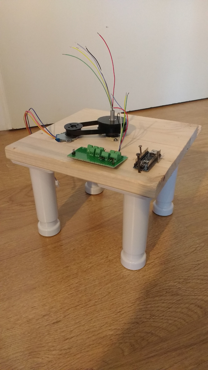
Previously on agayon.be, I mentioned a new small project. I started to build a SLAM device. After several tests and trials, I managed to assemble a small rotating platform. The lowest part is made of several elements:
- a wooden platform
- a 5V stepper motor (BYJ48)
- an electronic breadboard used for the connections
- an arduino nano compatible board
- a slip ring
The rotating part hold the Lidar and a 5V servo motor.
Pictures and video
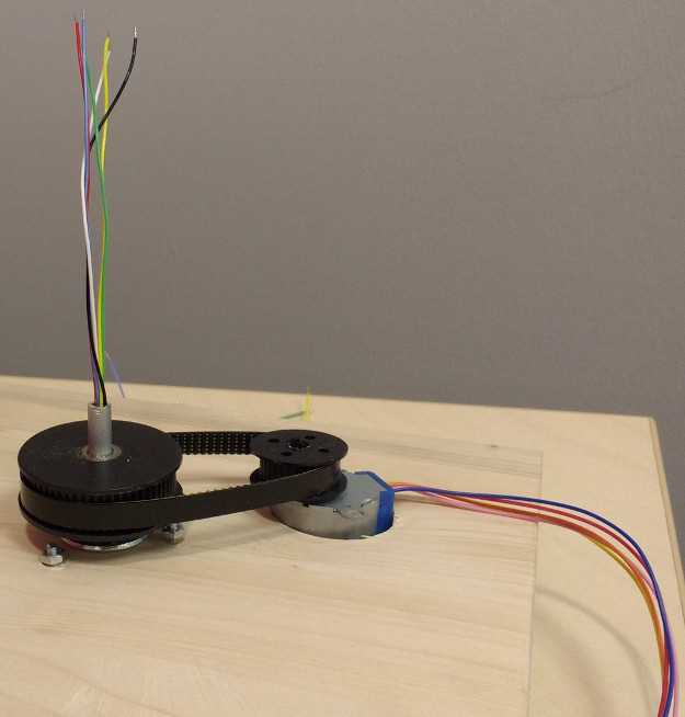
The lower part of the platform: stepper motor, timing belt and pulleys
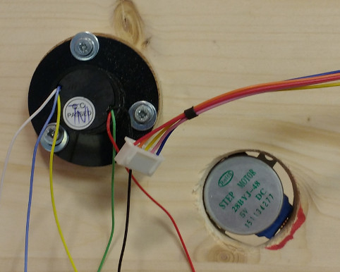
On the other face, a slip ring allows the transmission of electric signal between static and rotating parts
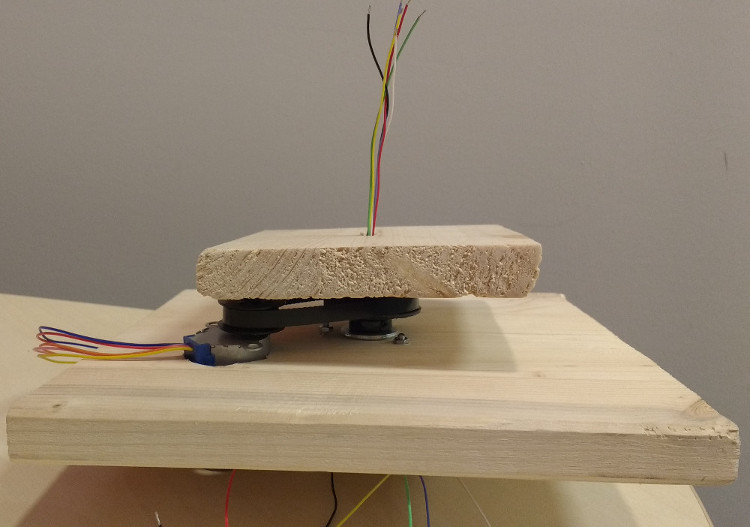
This wood board gives a better idea of the final product
The Lidar is able to rotate at 180°
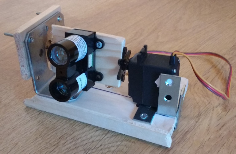
The assembled platform with the Arduino nano
Finally, a small video with the whole assembled parts
The Lidar performs the distance measurements every 500 ms.
The laser can rotate on a horizontal plane at 360° and at 180° on a vertical plane. My aim is to obtain a picture of a hemisphere. The Arduino transmits the data by batch. It is planned to interface this device with the BreezyLidar and BreezySLAM Python libraries. Therefore, it will communicate through a serial interface similarly to other popular Lidar like Hokuyo URG-04LX or the RP Lidar.
Code
Arduino nano
The Nano controls:
- the Lidar
- the servo
/* Distance measurments
  by Arnaud Joset <www.agayon.be>
  This example code is released under the GPLV3 licence.
  This code is inspired by the work of:
  - Sweep by BARRAGAN <http://barraganstudio.com>
  - LIDARLite Arduino Library GetDistancePwm (Garmin)

  modified 30 March 2017
  by Arnaud Joset
*/

#include <Servo.h>

Servo myservo;  // create servo object to control a servo
// twelve servo objects can be created on most boards

int mini = 0;// minimum position Servo
int maxi = 180; // Maximum position Servo
int pos = 90; // variable to store the servo position

boolean Servo_state = 1;

unsigned long pulseWidth;
unsigned long currentMillis, previousServoMillis, previousLidarMillis;
unsigned int intervalServo = 10, intervalLidar = 500 ;
int triggerPin = 2;
int monitorPin = 3;


void setup() {

  Serial.begin(9600); // Start serial communications

  // TRIGGER  = RESISTANCE 1k OHM = YELLOW
  //  MONITOR = NO RESISTANCE

  pinMode(triggerPin, OUTPUT); // Set pin 2 as trigger pin
  digitalWrite(triggerPin, LOW); // Set trigger LOW for continuous read

  pinMode(monitorPin, INPUT); // Set pin 3 as monitor pin
  Serial.println("Start");


  myservo.attach(9);  // attaches the servo on pin 9 to the servo object
  // pin 9 et 10 pour servo shield
}

void loop() {
  lidar_test();
}


void lidar_test() {
  currentMillis = millis();
  if (currentMillis - previousServoMillis > intervalServo ) {
    previousServoMillis = currentMillis;
    Servo_state = setServo(Servo_state);
  }
  if (currentMillis - previousLidarMillis > intervalLidar ) {
    previousLidarMillis = currentMillis;
    pulseWidth = pulseIn(monitorPin, HIGH); // Count how long the pulse is high in microseconds
    //Serial.print("Pulsewidth ");
    //Serial.println(pulseWidth);
    // If we get a reading that isn't zero, let's print it
    if (pulseWidth != 0)
    {
      pulseWidth = pulseWidth / 10; // 10usec = 1 cm of distance
      Serial.print("Distance : ");
      Serial.print(pulseWidth); // Print the distance
      Serial.println(" cm"); // Print the distance
    }
  }
}

//////////////////////////////////////////
// ---- SERVO ---
boolean setServo(boolean Servo_state)// balayage servo de 20 à 180°
{
  int increment = 1;
  if (Servo_state == 1) {
    // Serial.println("Rising ngle");
    pos += increment;
  }
  else
  {
    // Serial.println("Falling angle");
    pos -= increment;
  }
  //Serial.print("Pos = ");
  //Serial.println(pos);
  if (pos <= mini) {
    Servo_state = 1;
    pos = mini;

  }
  if (pos >= maxi) {
    Servo_state = 0;
    pos = maxi;

  }

  myservo.write(pos);
  return Servo_state;

}
The Mega with motor shield V2.3
This board controls the stepper motor.
/*
This is a test sketch for the Adafruit assembled Motor Shield for Arduino v2
It won't work with v1.x motor shields! Only for the v2's with built in PWM
control

For use with the Adafruit Motor Shield v2
---->   http://www.adafruit.com/products/1438
*/


#include <Wire.h>
#include <Adafruit_MotorShield.h>
#include "utility/Adafruit_MS_PWMServoDriver.h"

// Create the motor shield object with the default I2C address
Adafruit_MotorShield AFMS = Adafruit_MotorShield();
// Or, create it with a different I2C address (say for stacking)
// Adafruit_MotorShield AFMS = Adafruit_MotorShield(0x61);

// Connect a stepper motor with 513 steps per revolution (xx degree)
// to motor port #2 (M3 and M4)
Adafruit_StepperMotor *myMotor = AFMS.getStepper(513, 2);


/*
 * Wiring stepper 28 BYJ-48 5V
 * bleue: M4 top
 * pink: M3 bottom
 * red : GND
 * orange: M3 top
 * yellow : M4 bottom
 * On the mega, the top and bottom refer to the position of the connection
   when the user can read the text on the shield.
*/
void setup() {
  Serial.begin(9600);           // set up Serial library at 9600 bps
  Serial.println("Stepper test!");

  AFMS.begin();  // create with the default frequency 1.6KHz
  //AFMS.begin(1000);  // OR with a different frequency, say 1KHz

  myMotor->setSpeed(25);  // 5 rpm
}

void loop() {

 myMotor->step(1000, FORWARD, DOUBLE);
 test();

}


void test(){

   Serial.println("Single coil steps");
  myMotor->step(1000, FORWARD, SINGLE);
  myMotor->step(1000, BACKWARD, SINGLE);

  Serial.println("Double coil steps");
  myMotor->step(1000, FORWARD, DOUBLE);
  myMotor->step(1000, BACKWARD, DOUBLE);
}
Future
The following steps are:
- Use an encoder disk to determine the direction of measurement.
- Write the measurement procedure and the serial protocol in order to use the BreezySLAM library.